
 English
  Polish
  Czech
Czech  German
  Spanish
  Italian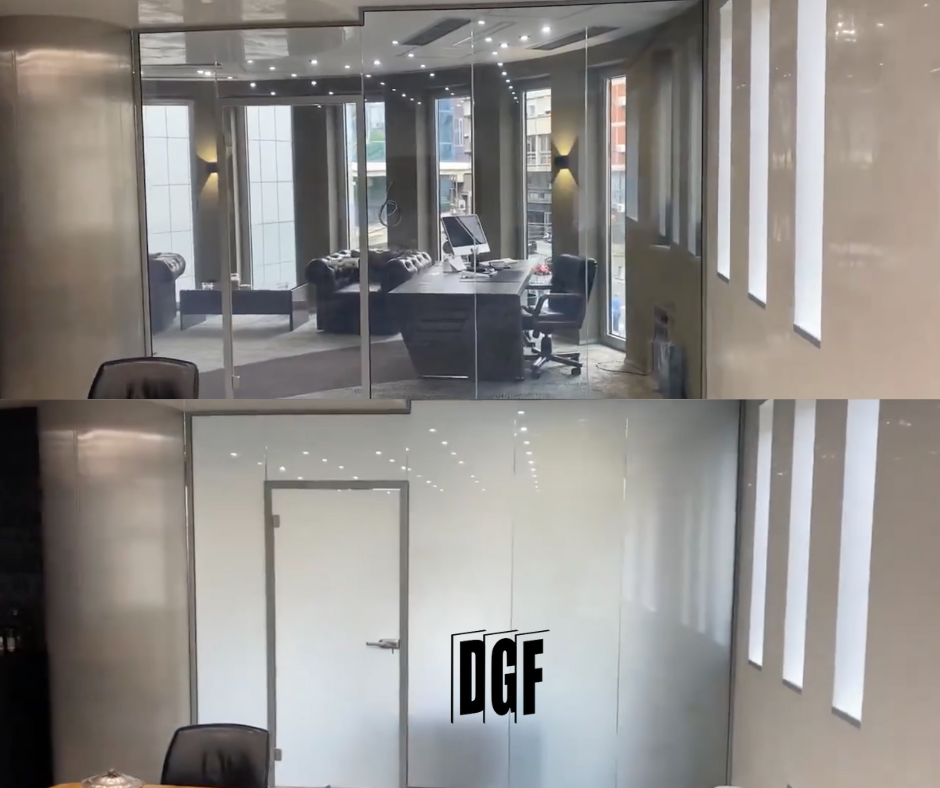
With conventional glazing some decisions can be resolved on site. An active pane allows less flexibility because the PDLC layer, inactive border, connection and cable are created during manufacture. A dimensional or orientation error is not a cosmetic adjustment.
Good installation therefore does not begin when a team arrives with suction lifters. It begins with a shared drawing on which the architect, frame supplier, electrician and DGF see the same cable edge, power-supply location and final geometry.
1. Concept stage: where and why should the glass switch?
Begin with the function: corridor-to-room sightline, bathroom privacy, consulting-room screening or several independent zones. This defines active area, product, circuit count and controls. Not every part of the glazing needs to be active.
Also establish whether this is a new partition, window, door, existing frame or completed-space retrofit. The complete-element construction and requirements affect glass build-up, while ceiling and wall access affect the power route.
2. Survey and approved manufacturing drawing
A survey covers more than width and height. Tolerances, rebate depth, glazing clearances, shape, holes, cut-outs, orientation, connection side, support and fixing information are required. Data must reflect the actual construction, not only a visualisation.
The manufacturing drawing should identify every pane and its orientation from a defined viewpoint. For zoned glass it shows division lines and corresponding circuits. Approval closes the option to move a hole, zone or cable freely.
- final dimensions and tolerances
- pane build-up and weight
- holes, cut-outs and inactive perimeter
- cable-exit direction and length
- face and installation-sequence identification
3. Preparing framing, wiring and power supply
The frame must accommodate actual glass thickness and weight, provide required support and allow the connection to leave safely. The edge must not be exposed to incompatible materials, persistent moisture or pressure that can damage the cable. The exact detail follows the selected system and conditions.
The power supply and control components should be in a dry, accessible location where diagnosis and replacement do not require dismantling a finished ceiling. Cable routes should be documented and connection points protected. For multiple panes, circuits should be labelled before connection.
In practice: A power-supply position should not be selected only because space is available. Environmental conditions, permitted distances for the specific system, ventilation, service access and building-services coordination all matter.
4. Delivery, handling and glazing
Before delivery, verify the handling route, structural readiness, storage location, personnel and equipment required. An active pane is a glass product and must be handled according to its weight, size and build-up.
During glazing, orientation, setting blocks, clearances, active edge and cable require particular attention. The cable must not carry glass weight, be kinked or trapped between hard elements. Seals and materials touching the laminate must match the approved detail.
5. Electrical connection and controls
Connection follows documentation for the specific system and site electrical requirements. The power supply must match the load and circuits must correspond to physical panes or zones. Glass should not be powered by an arbitrary device simply because its nominal voltage seems similar.
Local controls are tested before app or BMS integration. This separates glass and power operation from the supervisory system configuration. In multi-zone projects, scenes should have clear names and manual operation should not disappear without good reason.
| Test | What to check | Outcome |
|---|---|---|
| OFF state | Uniform frosted state and design compliance | Every pane or zone identified |
| ON state | Switching of every specified area | No crossed circuits |
| Local control | Switch, label and logical response | Operation possible without an app |
| Scenes and integration | Sequence, initial and failure states | Functional test record |
6. Handover and user documentation
Handover should confirm not only visual appearance but edge condition, glazing quality, circuit labelling, power-supply access and behaviour during a power cut. Users need to know how to switch the glass, what to avoid and where to report a fault.
Documentation should include the pane schedule, circuit diagram or description, service-component locations, cleaning instructions and products used in the project. Future diagnosis then avoids ceiling demolition and guessing which cable serves which pane.